Page History
| Sv translation | |||||||||||
|---|---|---|---|---|---|---|---|---|---|---|---|
| |||||||||||
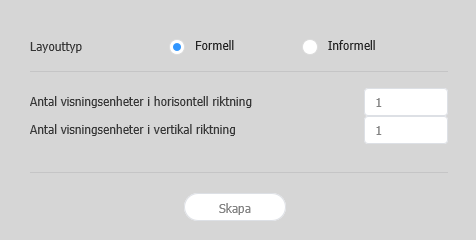
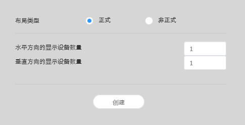
레이아웃 설정하기MagicInfo Server에서 Layout Editor를 실행하면 레이아웃 설정 창이 실행됩니다. 해당 창에서 레이아웃 기본 설정 후
| 비디오월 레이아웃 |
| Stylesheet | ||
|---|---|---|
| ||
|
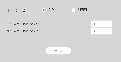
레이아웃 타입 - 정형: 장치를 2X2, 3X4 등 직사각형 형태로 정렬하여 고정된 형태의 비디오월을 구성합니다.
- 비정형: 장치를 사용자가 원하는 형태로 자유롭게 배치할 수 있습니다.
가로 디스플레이
수 비디오월 레이아웃을 구성할 장치의 가로 개수가 표시됩니다. 세로 디스플레이
장치 수 비디오월 레이아웃을 구성할 장치의 세로 개수가 표시됩니다.
레이아웃 구성하기
레이아웃 모드에서 비디오월 레이아웃을 원하는대로 구성할 수 있습니다.
X 위치, Y 위치: 섹션의 가로, 세로 위치가 표시됩니다.
Info title 참고 X, Y 위치 값은 확인만 가능하며, 수정할 수 없습니다.
회전 각도: 섹션의 배치 각도를 설정할 수 있습니다. 스크롤 바를 좌우로 드래그해 원하는 각도를 설정하세요.
Info title 참고 다음과 같은 방법으로도 회전 각도를 지정할 수 있습니다.
- 편집 영역에서 섹션을 선택하면 나타나는
 클릭한 후 원하는 각도로 움직이세요.
 - 편집 영역에서 섹션을 선택한 후 도구 모음에서 각도 설정 도구(
 )로 회전각을 설정하세요.
 - 편집 영역에서 섹션을 선택한 후 도구 모음에서
 클릭하면 섹션을 90도씩 회전합니다.
- 편집 영역에서 섹션을 선택하면 나타나는
장치 속성 설정하기
속성 탭에 선택한 장치의 상세 정보가 나타나면 장치 위치 정보를 원하는 대로 설정하세요.
디스플레이 장치 정보는 확인만 가능하며, 수정할 수 없습니다.
- 모델명: 장치의 모델명이 표시됩니다.
- 가로 해상도: 장치의 가로 해상도 값이 표시됩니다.
- 세로 해상도: 장치의 세로 해상도 값이 표시됩니다.
- 가로 크기: 장치의 너비를 표시합니다.
- 패널 수평 크기: 장치에서 베젤의 좌우 두께를 제외한 가로 크기가 표시됩니다.
- 베젤 좌우 두께: 장치의 좌우 베젤 두께가 표시됩니다.
- 세로 크기: 장치의 높이를 표시합니다.
- 패널 수직 크기: 장치에서 베젤의 상하 두께를 제외한 세로 크기가 표시됩니다.
- 베젤 상하 두께: 장치의 상하 베젤 두께가 표시됩니다.
장치의 위치 정보를 설정할 수 있습니다.
- 중앙점 X위치: 장치 중앙의 가로 위치를 설정할 수 있습니다. 원하는 위치 값을 입력하면 해당 장치의 위치가 변경됩니다.
- 중앙점 Y위치: 장치 중앙의 세로 위치를 설정할 수 있습니다. 원하는 위치 값을 입력하면 해당 장치의 위치가 변경됩니다.
회전 각도: 장치의 배치 각도를 설정할 수 있습니다. 스크롤 바를 좌우로 드래그해 원하는 각도를 설정하세요.
Info title 참고 다음과 같은 방법으로도 회전 각도를 지정할 수 있습니다.
- 편집 영역에서 장치를 선택하면 나타나는 클릭한 후 원하는 각도로 움직이세요.
- 편집 영역에서 장치를 선택한 후 도구 모음에서 각도 설정 도구()로 회전각을 설정하세요.
- 편집 영역에서 장치를 선택한 후 도구 모음에서 클릭하면 장치를 90도씩 회전합니다.
- 편집 영역에서 장치를 선택하면 나타나는
- 첫 번째 X위치: 장치 위쪽 왼편의 가로 위치를 설정할 수 있습니다.
- 첫 번째 Y위치: 장치 위쪽 왼편의 세로 위치를 설정할 수 있습니다.
- 두 번째 X위치: 장치 위쪽 오른편의 가로 위치를 설정할 수 있습니다.
- 두 번째 Y위치: 장치 위쪽 오른편의 세로 위치를 설정할 수 있습니다.
- 세 번째 X위치: 장치 아래쪽 오른편의 가로 위치를 설정할 수 있습니다.
- 세 번째 Y위치: 장치 아래쪽 오른편의 세로 위치를 설정할 수 있습니다.
- 네 번째 X위치: 장치 아래쪽 왼편의 가로 위치를 설정할 수 있습니다.
네 번째 Y위치: 장치 아래쪽 왼편의 세로 위치를 설정할 수 있습니다.
Info 장치의 위치는 편집 영역에서 장치를 선택한 후 원하는 위치로 드래그하여 설정할 수도 있습니다.
장치 맵핑하기
레이아웃 모드에서 설정이 완료되면 맵핑 모드를 클릭하세요.
맵핑 모드에 진입하면 실제 장치 화면에 ID가 나타납니다. 이 ID를 사용하여 편집 영역의 가상 장치와 실제 장치를 연동할 수 있습니다.
| Info | ||
|---|---|---|
| ||
장치 ID는 해당 장치 그룹에 속한 장치 개수에 따라 부여됩니다. 예를 들어, 장치 그룹에 모두 10개의 장치가 있다면 각 장치에는 01~10 까지의 ID가 나타납니다. |
- 편집 영역에서 원하는 장치를 선택하세요.
- 속성 탭에 선택한 장치의 상세 정보가 나타나면 실제 장치에서 확인한 ID를 입력하세요.
편집 영역의 해당 장치 화면에 입력한 ID가 표시됩니다.
| Info | ||
|---|---|---|
| ||
|
레이아웃 미세 조정하기
맵핑 모드에서 설정이 완료되면 미세조정 모드를 클릭하세요.
실제 장치의 위치 설정에 미세한 조정이 필요한 경우 미세조정 모드를 사용하여 간편하게 수정할 수 있습니다.
| Info | ||
|---|---|---|
| ||
|
- 편집 영역에서 원하는 요소(섹션 또는 장치)를 선택하세요.
- 속성 탭에 선택한 요소의 상세 정보가 나타나면 위치 값을 수정하세요.
- 도구 모음에서
 클릭하세요.
변경 사항이 적용됩니다.
| Info | ||
|---|---|---|
| ||
|
MagicInfo Server에 배포하기
비디오월 레이아웃 구성이 완료되면 작업 완료를 클릭하세요.
Info 맵핑 모드에서 장치 ID 설정을 완료해야 작업 완료 단계를 사용할 수 있습니다.
- 비디오월 레이아웃을 MagicInfo Server로 배포할 것인지 확인하는 창이 나타나면 예를 클릭하세요.
구성한 비디오월 레이아웃이 MagicInfo Server로 배포되며, 해당 장치 그룹에 적용됩니다Info title 참고
비디오월 레이아웃이 정형일 때는 미리 설정된 레이아웃 구성을 확인만 할 수 있으며, 편집할 수 없습니다
장치 정렬하기
- 편집 영역에서 원하는 장치를 선택하세요.
- 원하는 방법을 선택해 장치를 정렬하세요.
- 방법 1: 메뉴 바의 편집 > 정렬을 클릭한 후 원하는 정렬 기준을 선택하세요.
- 방법 2: 편집 영역의 장치를 마우스 오른쪽 버튼으로 클릭하면 나타나는 메뉴에서 정렬을 선택한 후 정렬 기준을 지정하세요.
- 방법 3: 도구 모음에서 원하는 정렬 아이콘(
 )을 클릭하세요.
장치 배치하기
- 편집 영역에서 원하는 장치를 선택하세요.
- 원하는 방법을 선택해 장치를 배치하세요.
- 방법 1: 메뉴 바의 편집 > 순서 변경을 클릭한 후 원하는 배치 순서를 선택하세요.
- 방법 2: 편집 영역의 장치를 마우스 오른쪽 버튼으로 클릭하면 나타나는 메뉴에서 순서를 선택한 후 배치 순서를 지정하세요.
- 방법 3: 도구 모음에서 원하는 배치순서 아이콘(
 )을 클릭하세요.
섹션 속성 설정하기
| Info | ||
|---|---|---|
| ||
Layout Editor에서는 같은 장치 그룹의 모든 장치를 하나의 섹션으로 인식합니다. |
편집 영역에서 섹션을 선택하세요.
| Info | ||
|---|---|---|
| ||
편집 영역 중 가상 장치 화면 이외의 빈 영역을 선택한 상태에서 장치를 클릭하면 섹션이 선택됩니다. |
속성 탭에 섹션 상세 정보가 나타나면 섹션의 위치 정보(회전 각도)를 원하는 대로 설정하세요.
선택한 레이아웃 타입에 따라 레이아웃 구성 방법이 다릅니다. 이 사용 설명서에서는 비정형을 기준으로 설명합니다.
장치 목록에서 원하는 장치를 선택해 편집 영역으로 드래그하세요.
Info title 참고 레이아웃 타입을 정형으로 선택한 경우 이 과정이 생략됩니다.
Stylesheet class screen 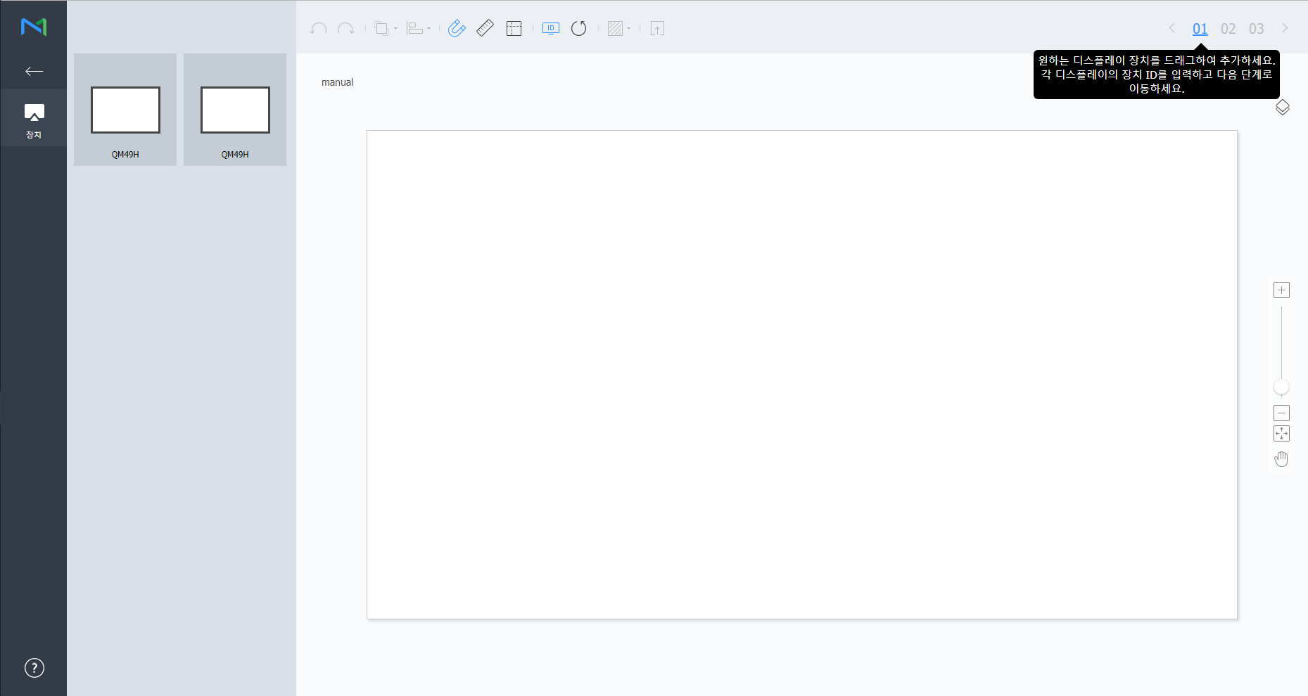
각 장치에 장치 ID를 입력한 후 02를 클릭하세요.
Stylesheet class screen 
1 입력한 장치 ID를 장치 화면에 표시할 수 있습니다. 2 입력한 장치 ID를 초기화할 수 있습니다. 장치의 세부 위치를 조절한 후 03을 클릭하세요.
Stylesheet class screen 
1  : 마지막에 실행한 작업을 취소하여 이전 상태로 되돌릴 수 있습니다.
 : 실행 취소한 작업을 다시 실행할 수 있습니다.
 : 여러 개의 장치들을 원하는 정렬 기준에 맞게 한번에 정렬할 수 있습니다.
 : 장치가 눈금에 자동으로 맞춰 정렬됩니다.
 : 눈금자를 표시합니다.
 : 안내선을 표시합니다.
 : 장치에 표시할 테스트용 패턴을 선택할 수 있습니다.
 : 적용된 레이아웃을 장치에서 미리 볼 수 있습니다.
2 장치의 위치를 미세하게 조절할 수 있습니다. 3 편집 화면의 보기 비율을 확대/축소할 수 있습니다. 슬라이드 바를 조절해 원하는 비율로 설정하세요. 4  : 편집 화면의 비율과 위치를 창 사이즈에 맞게 조정하여 장치를 한눈에 확인할 수 있습니다.
 : 선택된 장치를 이동할 수 있습니다.
5 VWL Layout Editor의 버전 및 오픈 소스 라이선스를 확인할 수 있습니다. - 레이아웃 구성이 끝나면 예를 클릭하세요.
- 해당 비디오월 레이아웃이 서버에 저장됩니다.
| Sv translation | |||||||||||
|---|---|---|---|---|---|---|---|---|---|---|---|
| |||||||||||
Layout settingsIf you launch Layout Editor from MagicInfo Server, the Layout setting window appears. Configure basic layout settings from the window, and then click Create.
| |||||||||||
| Content Name | Enter a new videowall layout name. | VideoWall Layout |
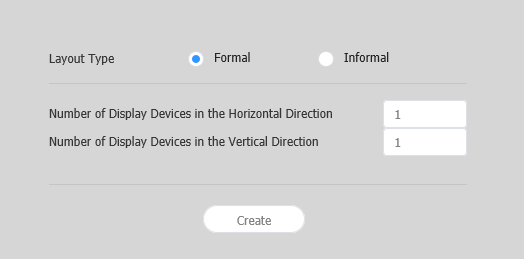
| Layout types |
|
- Informal: Customize the arrangement of devices to suit your preferences.
Number of Display Devices in the Horizontal Direction The number of horizontal devices in a videowall layout is shown. Number of Display Devices in the Vertical Direction The number of vertical devices in a videowall layout is shown.
Configuring a layout
Configure a videowall layout as desired using Layout Mode.
Position X, Position Y: Horizontal and vertical locations of a section are shown.
Info title Note X and Y values are read only and cannot be edited.
Rotation: Specify the arrangement angle for a section. Drag the scroll bar left or right to specify the angle.
Info title Note Alternative ways to specify the rotation angle are as follows:
- Select a section from the edit section, and then click and move the displayed until a desired angle is reached.
- Select a section from the edit section, and then specify the rotation angle using the angle setting tool () on the toolbar.
- Select a section from the edit section, and then click on the toolbar to rotate the section. The section will rotate by 90 degrees each time the icon is clicked.
- Select a section from the edit section, and then click and move the displayed
Configuring device properties
When detailed information about the selected device appears in the Properties tab, configure information about the device location as desired.
Display device information is read only and cannot be edited.
- Model Name: A device model name is shown.
- Horizontal Resolution: The horizontal resolution for a device is shown.
- Vertical Resolution: The vertical resolution for a device is shown.
- Width: View the device width.
- Panel Horizontal Size: Device width is shown. The bezel thickness is excluded from the width.
- Bezel Top to Bottom Thickness: The bezel thickness on the left and right edges of a device is shown.
- Height: Device height is shown.
- Panel Vertical Size: View the device height with the bezel width excluded.
- Bezel Left to Right Thickness: The bezel thickness on the top and bottom of a device is shown.
Configure information about a device location.
- Center position X: Specify the horizontal location for the center of a device. Enter a location value. The device location will change.
- Center position Y: Specify the vertical location for the center of a device. Enter a location value. The device location will change.
Rotation: Specify the arrangement angle for a device. Drag the scroll bar left or right to specify the angle.
Info title Note Alternative ways to specify the rotation angle are as follows:
- Select a device from the edit section, and then click and move the displayed until a desired angle is reached.
- Select a device from the edit section, and then specify the rotation angle using the angle setting tool () on the toolbar.
- Select a device from the edit section, and then click on the toolbar to rotate the device. The device will rotate by 90 degrees each time the icon is clicked.
- Select a device from the edit section, and then click and move the displayed
- First X Position: Specify the horizontal location for the top left of a device.
- First Y Position: Specify the vertical location for the top left of a device.
- Second X Position: Specify the horizontal location for the top right of a device.
- Second Y Position: Specify the vertical location for the top right of a device.
- Third X Position: Specify the horizontal location for the bottom right of a device.
- Third Y Position: Specify the vertical location for the bottom right of a device.
- Fourth X Position: Specify the horizontal location for the bottom left of a device.
Fourth Y Position: Specify the vertical location for the bottom left of a device.
Info A device location can also be configured by dragging the device to a desired location in the edit section.
Mapping devices
After configuring the required settings in Layout Mode, click Mapping Mode.
An ID appears on the actual device screen as soon as Mapping Mode activates. Use the ID to control the virtual device screen in the edit section in conjunction with the actual device.
| Info | ||
|---|---|---|
| ||
Device IDs are assigned according to the number of devices that form a device group. For example, if a device group has ten devices, different IDs are displayed on each device in the range 01–10. |
- Select a device from the edit section.
- When detailed information about the selected device appears in the Properties tab, enter the ID found on the actual device.
The ID will be displayed on the device screen in the edit section.
| Info | ||
|---|---|---|
| ||
|
Finely adjusting layouts
After configuring the required settings in Mapping Mode, click Finetuning Mode.
To finely adjust location settings for an actual device, use Finetuning Mode to edit the settings.
| Info | ||
|---|---|---|
| ||
|
- Select an element (section or device) from the edit section.
- When detailed information about the selected element appears in the Properties tab, edit the location value.
- Click on the toolbar.
Changes will be applied.
| Info | ||
|---|---|---|
| ||
|
Deploying to MagicInfo Server
After configuring a videowall layout, click Complete.
Info Complete step is only available after a device ID is set in Mapping Mode.
- When prompted to confirm distribution of the VideoWall layout to MagicInfo Server, click Yes.
The VideoWall layout you configured will be deployed to MagicInfo Server and applied to selected device group(s)Info title Note
Under formal videowall layout mode, a predefined layout is read-only and cannot be edited.
Aligning devices
- Select a device from the edit section.
- Align devices using one of the following options:
- Option 1: Click Edit > Sort on the menu bar, and then select an alignment mode.
- Option 2: Right-click on a device in the edit section and select Sort. Next, specify the alignment mode.
- Option 3: Click the desired alignment icon () from the toolbar.
Arranging devices
- Select a device from the edit section.
- Arrange devices using one of the following options:
- Option 1: Click Edit > Order from the menu bar, and then select an arrangement order.
- Option 2: Right-click on a device in the edit section and select Order. Next, specify the arrangement order.
- Option 3: Click the desired arrangement order icon () from the toolbar.
Configuring section properties
| Info | ||
|---|---|---|
| ||
In Layout Editor, devices under a device group are recognized as a single section. |
Select a section from the edit section.
| Info | ||
|---|---|---|
| ||
To select a section, click on empty area other than the virtual device screen in the edit section and then click a device. |
When detailed section information appears in the Properties tab, change information about the section location (rotation angle) as desired.
Configuring layouts depends on the selected layout type. This user manual is based on the Informal type.
Select devices from the list and drag them into the editor section.
Info title Note This step will not be available if you chose the the Formal type for your layout.
Stylesheet class screen 
Enter the device ID for each device and click 02.
Stylesheet class screen 
1 Display the device ID on the relevant device screen. 2 Initialize the device ID for that device. Adjust the device positions and click 03.
Stylesheet class screen 
1 - : Undo the last command to revert back to the previous state.
- : Redo a command that has been undone.
- : Align several devices based on desired alignment criteria.
- : Automatically arrange devices to fit the grid.
- : Display the ruler.
- : Display the guides.
- : Select the test pattern to display on the device.
- : Preview the device with the layout applied.
2 Adjust the device position more precisely. 3 Zoom in or out the editor screen view. Use the slide bar to adjust the zoom level. 4 - : Adjust the aspect ratio and position of the editor to fit the window to overview devices.
- : Move the selected device.
5 You can review the VWL Layout Editor version and the open source license information. - After configuring the layout, click Yes.
- The VideoWall layout will be saved to the server.
| Sv translation | ||||||||||||||||||||||||||||||
|---|---|---|---|---|---|---|---|---|---|---|---|---|---|---|---|---|---|---|---|---|---|---|---|---|---|---|---|---|---|---|
| ||||||||||||||||||||||||||||||
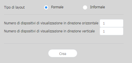
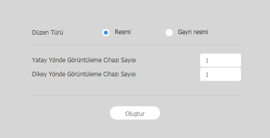
Impostazioni layoutSe si avvia Layout Editor da MagicInfo Server, viene visualizzata la finestra Impostazione layout. Configurare le impostazioni base del layout dalla finestra, quindi cliccare su Crea.
| ||||||||||||||||||||||||||||||
| Nome contenuto | Consente di immettere il nome di un nuovo layout videowall. | layout VideoWall |
| Tipi di layout |
|
- Informale: consente di personalizzare la disposizione dei dispositivi per adattarsi alle proprie preferenze.
Numero di dispositivi di visualizzazione in direzione orizzontale Indica il numero di dispositivi orizzontali in un
Layout VideoWall. Numero di dispositivi di visualizzazione in direzione verticale Indica il numero di dispositivi verticali in un
Layout VideoWall.
Configurazione di un layout
Configura un layout videowall come desiderato utilizzando Modalità layout.
Info title Nota Consente di configurare layout a seconda del tipo di layout selezionato. Questo manuale utente si basa sul tipo Informale.
Consente di selezionare dispositivi dall'elenco e di trascinarli nella sezione dell'editor.
Info title Nota
Nella modalità layout videowall formale, un layout predefinito è di sola lettura e non può essere modificato.
Allineamento di dispositivi
- Selezionare un dispositivo dalla sezione di modifica.
- Allineare i dispositivi utilizzando una delle opzioni seguenti:
- Opzione 1: Cliccare su Modifica > Ordina nella barra dei menu, quindi selezionare una modalità di allineamento.
- Opzione 2: Cliccare con il pulsante destro del mouse su un dispositivo nella sezione di modifica e selezionare Ordina. Dopo di che, specificare la modalità di allineamento.
- Opzione 3: Cliccare sull'icona di allineamento desiderata () dalla barra degli strumenti.
Disposizione di dispositivi
- Selezionare un dispositivo dalla sezione di modifica.
- Disporre i dispositivi utilizzando una delle opzioni seguenti:
- Opzione 1: Cliccare su Modifica > Ordina nella barra dei menu e selezionare un ordine di disposizione.
- Opzione 2: Cliccare con il pulsante destro del mouse su un dispositivo nella sezione di modifica e selezionare Ordina. Dopo di che, specificare l'ordine di disposizione.
- Opzione 3: Cliccare sull'icona dell'ordine di disposizione desiderata () dalla barra degli strumenti.
Configurazione delle proprietà sezione
| Info | ||
|---|---|---|
| ||
In Layout Editor, i dispositivi appartenenti a un gruppo di dispositivi vengono riconosciuti come una singola sezione. |
Selezionare una sezione dalla sezione di modifica.
| Info | ||
|---|---|---|
| ||
Per selezionare una sezione, cliccare sull'area vuota diversa dallo schermo virtuale del dispositivo nella sezione di modifica e cliccare su un dispositivo. |
Quando nella scheda Proprietà vengono visualizzate le informazioni dettagliate sulla sezione, modificare le informazioni sulla posizione della sezione (angolo di rotazione) come desiderato.
Posizione X, Posizione Y: indicano le posizioni orizzontale e verticale di una sezione.
Info title Nota I valori X e Y sono di sola lettura e non possono essere modificati.
Rotazione: consente di specificare l'angolo di disposizione per una sezione. Trascinare la barra di scorrimento verso sinistra o verso destra per specificare l'angolo.
Info title Nota Altri modi per specificare l'angolo di rotazione sono i seguenti:
- Selezionare una sezione dalla sezione di modifica e cliccare e spostare l'icona visualizzata fino a raggiungere l'angolo desiderato.
- Selezionare una sezione dalla sezione di modifica e specificare l'angolo di rotazione utilizzando lo strumento di impostazione angolo () della barra degli strumenti.
- Selezionare una sezione dalla sezione di modifica e cliccare su nella barra degli strumenti per ruotarla. La sezione ruoterà di 90° ogni volta che si clicca sull'icona.
- Selezionare una sezione dalla sezione di modifica e cliccare e spostare l'icona
Configurazione delle proprietà dispositivo
Quando nella scheda Proprietà vengono visualizzate le informazioni dettagliate sul dispositivo selezionato, configurare le informazioni sulla posizione del dispositivo come desiderato.
Le informazioni sul dispositivo di visualizzazione sono di sola lettura e non possono essere modificate.
- Nome modello: indica il nome modello del dispositivo.
- Risoluzione orizzontale: indica la risoluzione orizzontale per un dispositivo.
- Risoluzione verticale: indica la risoluzione verticale per un dispositivo.
- Larghezza: consente di visualizzare la larghezza del dispositivo.
- Dimensioni orizzontali pannello: indica la larghezza del dispositivo. La larghezza non include lo spessore della cornice.
- Spessore della cornice dall'alto al basso: indica lo spessore della cornice sui bordi sinistro e destro di un dispositivo.
- Altezza: indica l'altezza del dispositivo.
- Dimensioni verticali pannello: consente di visualizzare l'altezza del dispositivo escludendo la larghezza della cornice.
- Spessore della cornice da destra a sinistra: indica lo spessore della cornice in alto e in basso di un dispositivo.
Configura le informazioni sulla posizione di un dispositivo.
- Posizione centrale X: consente di specificare la posizione orizzontale per il centro di un dispositivo. Immettere un valore di posizione. La posizione del dispositivo cambierà.
- Posizione centrale Y: consente di specificare la posizione verticale per il centro di un dispositivo. Immettere un valore di posizione. La posizione del dispositivo cambierà.
Rotazione: consente di specificare l'angolo di disposizione per un dispositivo. Trascinare la barra di scorrimento verso sinistra o verso destra per specificare l'angolo.
Info title Nota Altri modi per specificare l'angolo di rotazione sono i seguenti:
- Selezionare un dispositivo dalla sezione di modifica e cliccare e spostare l'icona visualizzata fino a raggiungere l'angolo desiderato.
- Selezionare un dispositivo dalla sezione di modifica e specificare l'angolo di rotazione utilizzando lo strumento di impostazione angolo () della barra degli strumenti.
- Selezionare un dispositivo dalla sezione di modifica e cliccare su nella barra degli strumenti per ruotarlo. Il dispositivo ruoterà di 90° ogni volta che si clicca sull'icona.
- Selezionare un dispositivo dalla sezione di modifica e cliccare e spostare l'icona
- Prima posizione X: consente di specificare la posizione orizzontale per l'angolo superiore sinistro di un dispositivo.
- Prima posizione Y: consente di specificare la posizione verticale per l'angolo superiore sinistro di un dispositivo.
- Seconda posizione X: consente di specificare la posizione orizzontale per l'angolo superiore destro di un dispositivo.
- Seconda posizione Y: consente di specificare la posizione verticale per l'angolo superiore destro di un dispositivo.
- Terza posizione X: consente di specificare la posizione orizzontale per l'angolo inferiore destro di un dispositivo.
- Terza posizione Y: consente di specificare la posizione verticale per l'angolo inferiore destro di un dispositivo.
- Quarta posizione X: consente di specificare la posizione orizzontale per l'angolo inferiore sinistro di un dispositivo.
Quarta posizione Y: consente di specificare la posizione verticale per l'angolo inferiore sinistro di un dispositivo.
Info È possibile configurare la posizione di un dispositivo anche trascinando il dispositivo in una posizione desiderata all'interno della sezione di modifica.
Mappatura di dispositivi
Dopo aver configurato le impostazioni richieste in Modalità layout, cliccare su Modalità mappatura.
Nella schermata del dispositivo reale verrà visualizzato un ID non appena Modalità mappatura si attiva. Utilizzare l'ID per controllare lo schermo del dispositivo virtuale nella sezione di modifica in congiunzione con il dispositivo reale.
| Info | ||
|---|---|---|
| ||
Gli ID dispositivo vengono assegnati in base al numero di dispositivi che formano un gruppo di dispositivi. Ad esempio, se un gruppo di dispositivi dispone di dieci dispositivi, su ogni dispositivo vengono visualizzati ID diversi nell'intervallo compreso tra 01 e 10. |
- Selezionare un dispositivo dalla sezione di modifica.
- Quando nella scheda Proprietà vengono visualizzate le informazioni dettagliate sul dispositivo selezionato, immettere l'ID riportato sul dispositivo reale.
L'ID verrà visualizzato sullo schermo del dispositivo all'interno della sezione di modifica.
| Info | ||
|---|---|---|
| ||
|
Regolazione di precisione di layout
Dopo aver configurato le impostazioni richieste in Modalità mappatura, cliccare su Modalità sintonizzazione.
Per eseguire la regolazione di precisione delle impostazioni di posizione per un dispositivo reale, utilizzare Modalità sintonizzazione per modificare le impostazioni.
| Info | ||
|---|---|---|
| ||
|
- Selezionare un elemento (sezione o dispositivo) dalla sezione di modifica.
- Quando nella scheda Proprietà vengono visualizzate le informazioni dettagliate sull'elemento selezionato, modificare il valore di posizione.
- Cliccare su nella barra degli strumenti.
Le modifiche verranno applicate.
| Info | ||
|---|---|---|
| ||
|
Distribuzione a MagicInfo Server
Dopo aver configurato un layout videowall, cliccare su Completata.
Info Il passaggio Completata è disponibile solo dopo aver impostato l'ID di un dispositivo in Modalità mappatura.
- Quando viene richiesto di confermare la distribuzione del layout VideoWall a MagicInfo Server, cliccare su Sì.
Il layout VideoWall configurato verrà distribuito a MagicInfo Server e applicato a uno o più gruppi di dispositivi selezionati.
| language | de |
|---|
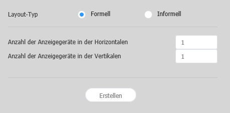
Layout-Einstellungen
Beim Starten des Layout Editor vom MagicInfo Server aus erscheint das Layout-Einstellung-Fenster. Konfigurieren Sie im Fenster grundlegende Layout-Einstellungen und klicken Sie dann auf Erstellen.
- Ein Videowall-Layout wird im Bearbeitungsbereich erstellt und der Layoutmodus aktiviert.
- Wenn Sie ein vorhandenes VideoWall-Layout verwenden, wird Layoutmodus gestartet, ohne das Fenster Layout-Einstellung anzuzeigen.
| Stylesheet | ||
|---|---|---|
| ||
|
Wählen Sie ein Videowall-Layout aus. Diese Option ist verfügbar, wenn die Gerätegruppe Geräte des gleichen Modells enthält.
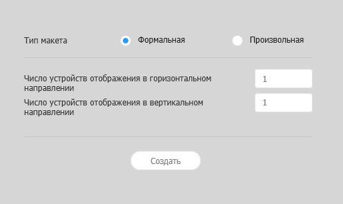
- Formell: Ordnen Sie im formalen Modus Geräte anhand einer vordefinierten Matrix wie zum Beispiel 2x2 und 3x4 an.
- Irregulär: Passen Sie die Anordnung der Geräte nach Ihren Wünschen an.
Konfigurieren eines Layouts
Konfigurieren Sie ein Videowall-Layout nach Bedarf im Layoutmodus.
| Info | ||
|---|---|---|
| ||
Im formalen Videowall-Layoutmodus ist ein vordefiniertes Layout schreibgeschützt und kann nicht bearbeitet werden. |
Ausrichten von Geräten
- Wählen Sie im Bearbeitungsbereich ein Gerät aus.
- Richten Sie Geräte mit einer der folgenden Optionen aus:
- Option 1: Klicken Sie in der Menüleiste auf Barbeiten > Sort. und wählen Sie dann eine Ausrichtung aus.
- Option 2: Klicken Sie mit der rechten Maustaste im Bearbeitungsbereich auf ein Gerät und wählen Sie dann Sort. aus. Legen Sie anschließend die Ausrichtung fest.
- Option 3: Klicken Sie in der Werkzeugleiste auf das gewünschte Ausrichtungssymbol ().
Anordnen von Geräten
- Wählen Sie im Bearbeitungsbereich ein Gerät aus.
- Ordnen Sie die Geräte mit einer der folgenden Optionen an:
- Option 1: Klicken Sie in der Menüleiste auf Bearbeiten > Sortieren und wählen Sie dann eine Anordnungsreihenfolge.
- Option 2: Klicken Sie mit der rechten Maustaste im Bearbeitungsbereich auf ein Gerät und wählen Sie dann Sortieren aus. Legen Sie anschließend die Anordnungsreihenfolge fest.
- Option 3: Klicken Sie in der Werkzeugleiste auf das gewünschte Anordnungssymbol ().
Konfigurieren der Bereichseigenschaften
| Info | ||
|---|---|---|
| ||
In Layout Editor werden Geräte in einer Gerätegruppe als ein einziger Bereich erkannt. |
Wählen Sie einen Bereich aus dem Bearbeitungsbereich aus.
| Info | ||
|---|---|---|
| ||
Klicken Sie zum Auswählen eines Bereichs im Bearbeitungsbereich auf einen leeren Bereich außerhalb des Bildschirms für das virtuelle Gerät und klicken Sie auf ein Gerät. |
Wenn detaillierte Bereichsinformationen auf der Registerkarte Eigenschaften angezeigt werden, ändern Sie die Informationen zur Bereichsposition (Drehwinkel) nach Bedarf.
Position X, Position Y: Die horizontalen und vertikalen Positionen eines Bereichs werden angezeigt.
Info title Hinweis Die X- und Y-Werte sind schreibgeschützt und können nicht bearbeitet werden.
Drehung: Legt den Anordnungswinkel eines Bereichs fest. Ziehen Sie die Bildlaufleiste nach links oder nach rechts, um den Winkel festzulegen.
Info title Hinweis Alternativ kann der Drehwinkel wie folgt festgelegt werden:
- Wählen Sie im Bearbeitungsbereich einen Bereich aus und klicken Sie dann auf das angezeigte Symbol und verschieben Sie es, bis der gewünschte Winkel erreicht ist.
- Wählen Sie im Bearbeitungsbereich einen Bereich aus und legen Sie dann den Drehwinkel mit dem Winkeleinstellungswerkzeug () in der Werkzeugleiste fest.
- Wählen Sie im Bearbeitungsbereich einen Bereich aus und klicken Sie dann in der Werkzeugleiste auf , um den Bereich zu drehen. Der Bereich wird bei jedem Klicken auf das Symbol um 90 Grad gedreht.
- Wählen Sie im Bearbeitungsbereich einen Bereich aus und klicken Sie dann auf das angezeigte Symbol
Konfigurieren von Geräteeigenschaften
Wenn detaillierte Informationen zum ausgewählten Gerät in der Registerkarte Eigenschaften angezeigt werden, konfigurieren Sie die Informationen zur Geräteposition nach Bedarf.
Die Informationen zum Anzeigegerät sind schreibgeschützt und können nicht bearbeitet werden.
- Modellname: Der Name eines Gerätemodells wird angezeigt.
- Horizontale Auflösung: Die horizontale Auflösung eines Geräts wird angezeigt.
- Vertikale Auflösung: Die vertikale Auflösung eines Geräts wird angezeigt.
- Breite: Ansehen der Gerätebreite.
- Horizontale Bildschirmgröße: Die Gerätebreite wird angezeigt. Die Stärke der Einfassung wird von der Breite abgezogen.
- Stärke der Einfassung von oben nach unten: Die Stärke der Einfassung am linken und rechten Rand des Geräts wird angezeigt.
- Höhe: Die Höhe des Geräts wird angezeigt.
- Vertikale Bildschirmgröße: Zeigen Sie die Höhe des Geräts ohne die Breite der Einfassung an.
- Stärke der Einfassung von links nach rechts: Die Stärke der Einfassung am oberen und unteren Rand des Geräts wird angezeigt.
Konfigurieren Sie Informationen zur Geräteposition.
- Mittelposition X: Legt die horizontale Position der Mitte eines Geräts fest. Geben Sie einen Positionswert ein. Die Geräteposition wird geändert.
- Mittelposition Y: Legt die vertikale Position der Mitte eines Geräts fest. Geben Sie einen Positionswert ein. Die Geräteposition wird geändert.
Drehung: Legt den Anordnungswinkel eines Geräts fest. Ziehen Sie die Bildlaufleiste nach links oder nach rechts, um den Winkel festzulegen.
Info title Hinweis Alternativ kann der Drehwinkel wie folgt festgelegt werden:
- Wählen Sie im Bearbeitungsbereich ein Gerät aus und klicken Sie dann auf das angezeigte Symbol und verschieben Sie es, bis der gewünschte Winkel erreicht ist.
- Wählen Sie im Bearbeitungsbereich ein Gerät aus und legen Sie dann den Drehwinkel mit dem Winkeleinstellungswerkzeug () in der Werkzeugleiste fest.
- Wählen Sie im Bearbeitungsbereich ein Gerät aus und klicken Sie dann in der Werkzeugleiste auf , um das Gerät zu drehen. Das Gerät wird bei jedem Klicken auf das Symbol um 90 Grad gedreht.
- Wählen Sie im Bearbeitungsbereich ein Gerät aus und klicken Sie dann auf das angezeigte Symbol
- Erste X-Position: Legt die horizontale Position der oberen linken Ecke eines Geräts fest.
- Erste Y-Position: Legt die vertikale Position der oberen linken Ecke eines Geräts fest.
- Zweite X-Position: Legt die horizontale Position der oberen rechten Ecke eines Geräts fest.
- Zweite Y-Position: Legt die vertikale Position der oberen rechten Ecke eines Geräts fest.
- Dritte X-Position: Legt die horizontale Position der unteren rechten Ecke eines Geräts fest.
- Dritte Y-Position: Legt die vertikale Position der unteren rechten Ecke eines Geräts fest.
- Vierte X-Position: Legt die horizontale Position der unteren linken Ecke eines Geräts fest.
Vierte Y-Position: Legt die vertikale Position der unteren linken Ecke eines Geräts fest.
Info Eine Geräteposition kann auch konfiguriert werden, indem das Gerät im Bearbeitungsbereich an die gewünschte Position gezogen wird.
Zuordnen von Geräten
Klicken Sie nach dem Konfigurieren der erforderlichen Einstellungen im Layoutmodus auf Zuordnungsmodus.
Sobald der Zuordnungsmodus aktiviert ist, wird auf dem Bildschirm des realen Geräts eine Kennung angezeigt. Steuern Sie mit der Kennung den Bildschirm des virtuellen Geräts im Bearbeitungsbereich in Verbindung mit dem realen Gerät.
| Info | ||
|---|---|---|
| ||
Gerätekennungen werden entsprechend der Anzahl der Geräte, die eine Gerätegruppe bilden, zugewiesen. Wenn eine Gerätegruppe zum Beispiel aus zehn Geräten gesteht, werden auf den Geräten jeweils unterschiedliche Kennungen im Bereich 01–10 angezeigt. |
- Wählen Sie im Bearbeitungsbereich ein Gerät aus.
- Wenn auf der Registerkarte Eigenschaften detaillierte Informationen zum ausgewählten Gerät angezeigt werden, geben Sie die Kennung ein, die sich am realen Gerät befindet.
Die Kennung wird im Bearbeitungsbereich auf dem Gerätebildschirm angezeigt.
| Info | ||
|---|---|---|
| ||
|
Feineinstellen von Layouts
Klicken Sie nach dem Konfigurieren der erforderlichen Einstellungen im Zuordnungsmodus auf Feinabstimmungsmodus.
Verwenden Sie zum Feineinstellen der Positionseinstellungen für ein reales Gerät den Feinabstimmungsmodus, um die Einstellungen zu bearbeiten.
| Info | ||
|---|---|---|
| ||
|
- Wählen Sie im Bearbeitungsbereich ein Element (Bereich oder Gerät) aus.
- Wenn auf der Registerkarte Eigenschaften detaillierte Informationen zum ausgewählten Element angezeigt werden, bearbeiten Sie den Positionswert.
- Klicken Sie in der Werkzeugleiste auf .
Die Änderungen werden übernommen.
| Info | ||
|---|---|---|
| ||
|
Bereitstellen auf dem MagicInfo Server
Klicken Sie nach dem Konfigurieren eines Videowall-Layouts auf abgeschl..
Info Der Schritt abgeschl. ist erst verfügbar, nachdem eine Gerätekennung im Zuordnungsmodus eingestellt wurde.
- Wenn Sie aufgefordert werden, die Verteilung des VideoWall-Layouts auf dem MagicInfo Server zu bestätigen, klicken Sie auf Ja.
Das von Ihnen konfigurierte VideoWall-Layout wird auf dem MagicInfo Server bereitgestellt und auf ausgewählte Gerätegruppen angewendet.
| language | zh_TW |
|---|
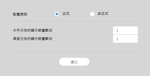
配置設定
如果您在 MagicInfo Server 中啟動 Layout Editor,會隨即出現配置設定視窗。在視窗中設定基本配置設定,然後按一下建立。
Questa fase non sarà disponibile se è stato scelto il tipo di layout regolare.
Stylesheet class screen 
Inserire l'ID di ciascun dispositivo e cliccare su 02.
Stylesheet class screen 
1 Consente di visualizzare l'ID del dispositivo sullo schermo del dispositivo pertinente. 2 Consente di avviare l'ID di un particolare dispositivo. Regolare le posizioni dei dispositivi e cliccare su 03.
Stylesheet class screen 
1 - : annulla l'ultimo comando per ripristinare lo stato precedente.
- : ripete un comando precedentemente annullato.
- : Consente di allineare diversi dispositivi in base a un criterio di allineamento desiderato.
- : Consente di disporre automaticamente i dispositivi per farli rientrare nella griglia.
- : Consente di visualizzare il righello.
- : Consente di visualizzare le guide.
- : Consente di selezionare il modello di prova da visualizzare sul dispositivo.
- : Consente di visualizzare l'anteprima del dispositivo con il layout applicato.
2 Consente di regolare più precisamente la posizione del dispositivo. 3 Consente di aumentare o diminuire la visualizzazione della schermata dell'editor. Utilizzare la barra di scorrimento per regolare le dimensioni di visualizzazione. 4 - : Consente di regolare il rapporto d'aspetto e la posizione dell'editor in base alle dimensioni della finestra per una panoramica dei dispositivi.
- : consente di spostare il dispositivo selezionato.
5 È possibile consultare la versione dell'editor del layout VWL e le informazioni di licenza open source. - Dopo aver configurato il layout, fare clic su Sì.
- Il layout VideoWall verrà salvato nel server.
| Sv translation | ||||||||||||||||||||||||||||||||||||||||||||||||||
|---|---|---|---|---|---|---|---|---|---|---|---|---|---|---|---|---|---|---|---|---|---|---|---|---|---|---|---|---|---|---|---|---|---|---|---|---|---|---|---|---|---|---|---|---|---|---|---|---|---|---|
| ||||||||||||||||||||||||||||||||||||||||||||||||||
|


| Sv translation | ||||||||||||||||
|---|---|---|---|---|---|---|---|---|---|---|---|---|---|---|---|---|
| ||||||||||||||||
Ustawienia układuPo uruchomieniu Layout Editor z MagicInfo Server wyświetla się okno ustawień Layout (Układ). Skonfiguruj w oknie podstawowe ustawienia układu, a następnie kliknij Create (Utwórz).
Konfiguracja układuKonfiguracja żądanego układu videowall z wykorzystaniem Layout Mode (Tryb układu). Uwaga:
Dopasowanie urządzeń
Porządkowanie urządzeń
Konfiguracja właściwości sekcjiUwaga:
Uwaga:
Konfiguracja właściwości urządzeń
Mapowanie urządzeńPo konfiguracji wymaganych ustawień w Layout Mode (Tryb układu) kliknij Mapping Mode (Tryb mapowania). Natychmiast po aktywacji Mapping Mode (Trybu mapowania) na ekranie urządzenia wyświetlane jest ID, które służy do sterowania ekranem wirtualnego urządzenia w sekcji edycji łącznie z urządzeniem. Uwaga:
Uwaga
Dostrajanie układówPo konfiguracji wymaganych ustawień w Mapping Mode (Tryb mapowania) kliknij Finetuning Mode (Tryb dostrajania). Trybu Finetuning Mode (Tryb dostrajania) używa się do dostrojenia ustawień lokalizacji urządzenia. Uwaga
Uwaga
Wysyłanie do MagicInfo Server
|


| Sv translation | |||||||||||||||||||||||||||||||||||||||||||||
|---|---|---|---|---|---|---|---|---|---|---|---|---|---|---|---|---|---|---|---|---|---|---|---|---|---|---|---|---|---|---|---|---|---|---|---|---|---|---|---|---|---|---|---|---|---|
| |||||||||||||||||||||||||||||||||||||||||||||
 | |||||||||||||||||||||||||||||||||||||||||||||
| 內容名稱 | 輸入新的 Videowall 配置名稱。 | ||||||||||||||||||||||||||||||||||||||||||||
| VideoWall 配置 | 選擇 Videowall 配置。裝置群組由相同型號的裝置所組成時,將可使用這個選項。
| ||||||||||||||||||||||||||||||||||||||||||||
| 型號名稱 | 會顯示將會組成 Videowall 配置的裝置類型。 | ||||||||||||||||||||||||||||||||||||||||||||
| Number of Display Devices in the Horizontal Direction | 會顯示在 Videowall 配置中的水平裝置數目。 | ||||||||||||||||||||||||||||||||||||||||||||
| Number of Display Devices in the Vertical Direction | 會顯示在 Videowall 配置中的垂直裝置數目。 |
| Info | ||
|---|---|---|
| ||
在正式 Videowall 配置模式下,預先定義的配置是唯讀狀態且無法編輯。 |
對齊裝置
- 從編輯區段中選擇裝置。
- 使用下列其中一個選項對齊裝置:
- 選項 1:按一下選單列上的編輯 > 排序,然後選擇對齊模式。
- 選項 2:以滑鼠右鍵按一下編輯區段中的裝置,然後選擇排序。接下來,指定對齊模式。
- 選項 3:在工具列中按一下所需的對齊圖示 ()。
排列裝置
- 從編輯區段中選擇裝置。
- 使用下列其中一個選項排列裝置:
- 選項 1:按一下選單列上的編輯 > 順序,然後選擇排列順序。
- 選項 2:以滑鼠右鍵按一下編輯區段中的裝置,然後選擇順序。接下來,指定排列順序。
- 選項 3:在工具列上按一下所需的排列順序圖示 ()。
設定區段屬性
| Info | ||
|---|---|---|
| ||
在 Layout Editor 中,會將在某個裝置群組下的裝置辨識為單一區段。 |
從編輯區段中選擇區段。
| Info | ||
|---|---|---|
| ||
若要選擇區段,請在編輯區段中按一下虛擬裝置螢幕以外的空白區域,然後按一下裝置。 |
詳細資訊區段資訊出現在屬性索引標籤中時,請視需要變更區段位置 (旋轉角度) 的相關資訊。
X 軸位置、Y 軸位置:顯示區段的水平與垂直位置。
Info title 附註 X 與 Y 值是唯讀狀態,無法編輯。
旋轉:為某個區段指定排列角度。將捲軸往左或往右拖曳,以指定角度。
Info title 附註 指定旋轉角度的其他方式如下所示:
- 從編輯區段中選擇區段,然後按一下並移動顯示的 ,直到達到所需的角度。
- 從編輯區段中選擇區段,然後使用工具列上的角度設定工具來指定旋轉角度 ()。
- 從編輯區段中選擇區段,然後按一下工具列上的 ,以旋轉區段。每次按一下圖示時,此區段將會旋轉 90 度。
- 從編輯區段中選擇區段,然後按一下並移動顯示的
設定裝置屬性
所選裝置的相關詳細資訊出現在屬性索引標籤中時,請視需要設定裝置位置的相關資訊。
顯示裝置資訊是唯讀狀態,無法編輯。
- 型號名稱:會顯示裝置型號名稱。
- 水平解析度:會顯示裝置的水平解析度。
- 垂直解析度:會顯示裝置的垂直解析度。
- 寬度:檢視裝置寬度。
- 面板水平大小:會顯示裝置寬度。會將寬度排除邊框寬度。
- 由上至下邊框的粗細:會顯示裝置左邊和右邊的邊框寬度。
- 高度:會顯示裝置高度。
- 面板垂直大小:檢視裝置高度 (排除邊框寬度)。
- 由左至右邊框的粗細:會顯示裝置上方和下方的邊框寬度。
設定裝置位置的相關資訊。
- 中心 X 軸位置:指定裝置中心的水平位置。輸入位置值。裝置位置將會變更。
- 中心 Y 軸位置:指定裝置中心的垂直位置。輸入位置值。裝置位置將會變更。
旋轉:為某個裝置指定排列角度。將捲軸往左或往右拖曳,以指定角度。
Info title 附註 指定旋轉角度的其他方式如下所示:
- 從編輯區段中選擇裝置,然後按一下並移動顯示的 ,直到達到所需的角度。
- 從編輯區段中選擇裝置,然後使用工具列上的角度設定工具來指定旋轉角度 ()。
- 從編輯區段中選擇裝置,然後按一下工具列上的 ,以旋轉裝置。每次按一下圖示時,此裝置將會旋轉 90 度。
- 從編輯區段中選擇裝置,然後按一下並移動顯示的
- 第一 X 軸位置:指定裝置左上方的水平位置。
- 第一 Y 軸位置:指定裝置左上方的垂直位置。
- 第二 X 軸位置:指定裝置右上方的水平位置。
- 第二 Y 軸位置:指定裝置右上方的垂直位置。
- 第三 X 軸位置:指定裝置右下方的水平位置。
- 第三 Y 軸位置:指定裝置右下方的垂直位置。
- 第四 X 軸位置:指定裝置左下方的水平位置。
第四 Y 軸位置:指定裝置左下方的垂直位置。
Info 在編輯區段中將裝置拖曳到所需位置,也可以設定裝置位置。
對應裝置
在設定配置模式中所需的設定後,按一下對應模式。
只要對應模式啟動,ID 就會出現在實際裝置螢幕上。使用 ID 可在編輯區段中控制虛擬裝置螢幕與實際裝置的關聯。
| Info | ||
|---|---|---|
| ||
會根據組成裝置群組的裝置數目來指定裝置 ID。例如,如果裝置群組有十個裝置,在每個裝置上會顯示不同 ID,範圍為 01–10。 |
- 從編輯區段中選擇裝置。
- 所選裝置的詳細資訊出現在屬性索引標籤中時,請輸入在實際裝置上找到的 ID。
ID 將會顯示在編輯區段中的裝置螢幕上。
| Info | ||
|---|---|---|
| ||
|
微調配置
在設定對應模式中所需的設定後,按一下微調模式。
若要微調實際裝置的位置設定,請使用微調模式以編輯設定。
| Info | ||
|---|---|---|
| ||
|
- 從編輯區段中選擇元素 (區段或裝置)。
- 所選元素的詳細資訊出現在屬性索引標籤中時,請編輯位置值。
- 按一下工具列上的 。
將會套用變更。
| Info | ||
|---|---|---|
| ||
|
部署至 MagicInfo Server
設定 Videowall 配置之後,按一下 完成。
Info 僅在對應模式中設定裝置 ID 後才可使用 完成 步驟。
- 提示確認將 VideoWall 配置發佈至 MagicInfo Server 時,請按一下是。
您設定的 VideoWall 配置將會部屬至 MagicInfo Server 並套用至所選裝置群組。
| language | es |
|---|
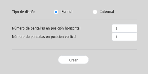
Configuración de diseño
Si se ejecuta Layout Editor desde MagicInfo Server, aparece la ventana Configuración de diseño. Configure los ajustes básicos del diseño en la ventana y, a continuación, haga clic en Crear.
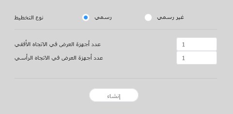
Layout types - رسمي: قم بترتيب الأجهزة في الوضع الرسمي باستخدام مصفوفة مسبقة التعريف مثل 2x2 و3x4.
- Informal: قم بتخصيص ترتيب الأجهزة ليلائم تفضيلاتك.
عدد أجهزة العرض في الاتجاه الأفقي يظهر عدد الأجهزة الأفقية في videowall layout. عدد أجهزة العرض في الاتجاه الرأسي يظهر عدد الأجهزة الرأسية في videowall layout. Info title ملاحظة يعتمد تكوين المخططات على نوع المخطّط المحدد. يعتمد دليل المستخدم هذا على النوع Informal.
حدّد أجهزة من القائمة واسحبها إلى قسم المحرر.
Info title ملاحظة لن تكون هذه الخطوة متاحة إذا اخترت النوع Formal بالنسبة للمخطط الخاص بك.
Stylesheet class screen 
أدخل معرّف الجهاز لكل جهاز وانقر فوق 02.
Stylesheet class screen 
1 لعرض معرّف الجهاز على شاشة الجهاز المعني. 2 تهيئة معرّف الجهاز لذلك الجهاز. عدّل مواقع الخزانة وانقر فوق 03.
Stylesheet class screen 
1 - : تراجع عن آخر أمر للعودة إلى الحالة السابقة.
- : أعد أمرًا تم التراجع عنه.
- : محاذاة عدة أجهزة بناءً على معايير المحاذاة المرغوب فيها.
- : ترتيب الأجهزة تلقائيًا لتلائم الشبكة.
- : عرض المسطرة.
- : عرض التوجيهات.
- : حدّد نمط الاختبار للعرض على الجهاز.
- : معاينة الجهاز مع المخطط المطبّق.
2 اضبط موقع الجهاز بشكل أكثر دقة. 3 قم بتكبير أو تصغير العرض لشاشة المحرر. استخدم شريط التمرير لضبط مستوى التكبير/التصغير. 4 - : اضبط الأبعاد النسبية ووضع المحرر بحيث يلائم النافذة من أجل الاطّلاع على نظرة عامة على الأجهزة.
- : نقل الجهاز المحدد.
5 يمكنك مراجعة إصدار محرر مخطط VWL ومعلومات الترخيص مفتوح المصدر. - بعد تكوين المخطط، انقر فوق Yes.
- سيتم حفظ مخطط VideoWall في الخادم.
| Sv translation | ||||||||||||||||||||||||||||||||||||||||||||||||||
|---|---|---|---|---|---|---|---|---|---|---|---|---|---|---|---|---|---|---|---|---|---|---|---|---|---|---|---|---|---|---|---|---|---|---|---|---|---|---|---|---|---|---|---|---|---|---|---|---|---|---|
| ||||||||||||||||||||||||||||||||||||||||||||||||||
|


| Sv translation | |||||||||||
|---|---|---|---|---|---|---|---|---|---|---|---|
| |||||||||||
| |||||||||||
| |||||||||||
| Nombre del contenido | Introduzca un nombre para el nuevo diseño de mural de vídeo. | Diseño VideoWall |
|
| Tipos de esquema |
|
Posición X, Posición Y: aparecen las ubicaciones horizontal y vertical de una sección.
Info title Nota Los valores X e Y son de solo lectura y no se pueden editar.
Giro: especifique el ángulo de disposición de la sección. Arrastre la barra de desplazamiento hacia la izquierda o la derecha para especificar el ángulo.
Info title Nota No obstante, existen otras formas de especificar el ángulo de rotación:
- Seleccione una sección en la sección de edición y, a continuación, haga clic y mueva el mostrado hasta lograr el ángulo deseado.
- Seleccione una sección en la sección de edición y, a continuación, especifique el ángulo de rotación usando la herramienta de ajuste de ángulos () de la barra de herramientas.
- Seleccione una sección en la sección de edición y, a continuación, haga clic en en la barra de herramientas para girar la sección. La sección girará 90 grados cada vez que haga clic en el icono.
- Seleccione una sección en la sección de edición y, a continuación, haga clic y mueva el
Configuración de las propiedades de dispositivos
Cuando aparezca información detallada sobre el dispositivo seleccionado en la pestaña Propiedades, configure la información sobre la ubicación del dispositivo como desee.
La información de pantalla es de solo lectura y no se puede editar.
- Nombre modelo: aparece el nombre de modelo del dispositivo.
- Resolución horizontal: aparece la resolución horizontal del dispositivo.
- Resolución vertical: aparece la resolución vertical del dispositivo.
- Anchura: vea la anchura del dispositivo.
- Tamaño horizontal del panel: aparece el ancho del dispositivo. El grosor de bisel no se incluye en la anchura.
- Grosor de bisel de arriba abajo: aparece el grosor de bisel de los bordes izquierdo y derecho de un dispositivo.
- Altura: aparece la altura del dispositivo.
- Tamaño vertical del panel: vea la altura del dispositivo sin incluir el bisel.
- Grosor de bisel de izquierda a derecha: aparece el grosor de bisel de los bordes superior e inferior de un dispositivo.
Configure información sobre la ubicación del dispositivo.
- Centrar posición X: especifique la ubicación horizontal del centro del dispositivo. Introduzca un valor de ubicación. La ubicación del dispositivo cambiará.
- Centrar posición Y: especifique la ubicación vertical del centro del dispositivo. Introduzca un valor de ubicación. La ubicación del dispositivo cambiará.
Giro: especifique el ángulo de disposición del dispositivo. Arrastre la barra de desplazamiento hacia la izquierda o la derecha para especificar el ángulo.
Info title Nota No obstante, existen otras formas de especificar el ángulo de rotación:
- Seleccione un dispositivo en la sección de edición y, a continuación, mueva el mostrado hasta lograr el ángulo deseado.
- Seleccione un dispositivo en la sección de edición y, a continuación, especifique el ángulo de rotación usando la herramienta de ajuste de ángulos () de la barra de herramientas.
- Seleccione un dispositivo en la sección de edición y, a continuación, haga clic en en la barra de herramientas para girar el dispositivo. El dispositivo girará 90 grados cada vez que haga clic en el icono.
- Seleccione un dispositivo en la sección de edición y, a continuación, mueva el
- Primera posición X: especifique la ubicación horizontal para la esquina superior izquierda del dispositivo.
- Primera posición Y: especifique la ubicación vertical para la esquina superior izquierda del dispositivo.
- Segunda posición X: especifique la ubicación horizontal para la esquina superior derecha del dispositivo.
- Segunda posición Y: especifique la ubicación vertical para la esquina superior derecha del dispositivo.
- Tercera posición X: especifique la ubicación horizontal para la esquina inferior derecha del dispositivo.
- Tercera posición Y: especifique la ubicación vertical para la esquina inferior derecha del dispositivo.
- Cuarta posición X: especifique la ubicación horizontal para la esquina inferior izquierda del dispositivo.
Cuarta posición Y: especifique la ubicación vertical para la esquina inferior izquierda del dispositivo.
Info La ubicación de un dispositivo también puede configurarse arrastrándolo hasta la ubicación deseada en la sección de edición.
Asignación de dispositivos
Tras configurar los ajustes necesarios en Modo Diseño, haga clic en Modo Asignación.
En cuanto se activa Modo Asignación, aparece un ID en el dispositivo. Utilice el ID para controlar la pantalla del dispositivo virtual en la sección de edición en combinación con el dispositivo real.
| Info | ||
|---|---|---|
| ||
Los ID de dispositivo se asignan de acuerdo con el número de dispositivos que forman un grupo de dispositivos. Por ejemplo, si un grupo cuenta con diez dispositivos, cada uno de ellos mostrará un ID distinto del 01 al 10. |
- Seleccione un dispositivo en la sección de edición.
- Si en la pestaña Propiedades aparece información detallada, introduzca el ID que muestra el dispositivo real.
El ID aparecerá en la pantalla del dispositivo en la sección de edición.
| Info | ||
|---|---|---|
| ||
|
Ajuste fino de diseños
Tras configurar los ajustes necesarios en Modo Asignación, haga clic en Modo Ajuste.
Para ajustar de forma precisa la ubicación de un dispositivo real, utilice Modo Ajuste para editar los ajustes.
| Info | ||
|---|---|---|
| ||
|
- Seleccione un elemento (sección o dispositivo) en la sección de edición.
- Cuando aparezca información detallada sobre el elemento seleccionado en la pestaña Propiedades, edite el valor de ubicación.
- Haga clic en en la barra de herramientas.
Los cambios se aplicarán.
| Info | ||
|---|---|---|
| ||
|
Implementación en MagicInfo Server
Tras configurar un diseño de mural de vídeo, haga clic en Completado.
Info El paso Completado solo está disponible tras haber establecido el ID de dispositivo en Modo Asignación.
- Cuando se le pida que confirme la distribución del diseño VideoWall en MagicInfo Server, haga clic en Sí.
El diseño VideoWall que ha configurado se implementará en MagicInfo Server y se aplicará al grupo (o grupos) de dispositivos seleccionado- e 3x4.
Configuración de un diseño
Configure un diseño de mural de vídeo como desee utilizando Modo Diseño.
| Info | ||
|---|---|---|
| ||
En el modo de diseño de mural de vídeo formal, el diseño predefinido es de solo lectura y no se puede editar. |
Alineación de dispositivos
- Seleccione un dispositivo en la sección de edición.
- Alinee los dispositivos utilizando una de las siguientes opciones:
- Opción 1: Haga clic en Editar > Ordenar en la barra de menús y, a continuación, seleccione un modo de alineación.
- Opción 2: Haga clic con el botón derecho del ratón en un dispositivo en la sección de edición y seleccione Ordenar. A continuación, especifique el modo de alineación.
- Opción 3: Haga clic en el icono de alineación deseado () en la barra de herramientas.
Disposición de dispositivos
- Seleccione un dispositivo en la sección de edición.
- Disponga los dispositivos utilizando una de las siguientes opciones:
- Opción 1: Haga clic en Editar > Ordenar en la barra de menús y, a continuación, seleccione un orden en la disposición.
- Opción 2: Haga clic con el botón derecho del ratón en un dispositivo en la sección de edición y seleccione Ordenar. A continuación, especifique el orden en la disposición.
- Opción 3: Haga clic en el icono del orden en la disposición deseado () en la barra de herramientas.
Configuración de las propiedades de sección
| Info | ||
|---|---|---|
| ||
En Layout Editor, los dispositivos de un grupo de dispositivos se reconocen como una única sección. |
Seleccione una sección en la sección de edición.
| Info | ||
|---|---|---|
| ||
Para seleccionar una sección, haga clic en un área vacía distinta de la pantalla del dispositivo virtual en la sección de edición y, a continuación, haga clic en un dispositivo. |
Cuando aparezca la información de la sección detallada en la pestaña Propiedades, cambie la información sobre la ubicación de la sección (ángulo de rotación) según sus deseos.
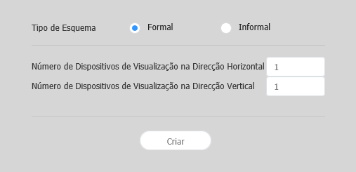
- Informal: Personalize a disposição dos dispositivos de acordo com as suas preferências.
Número de Dispositivos de Visualização na Direção Horizontal É apresentada a quantidade de dispositivos que se encontram na horizontal num esq. videowall. Número de Dispositivos de Visualização na Direção Vertical É apresentada a quantidade de dispositivos que se encontram na vertical num esq. videowall. Info title Nota A configuração de esquemas depende do tipo de esquema selecionado. Este manual do utilizador tem como base o tipo Informal.
Selecione dispositivos da lista e arraste-os para a secção do editor.
Info title Nota Este passo não estará disponível se optar pelo tipo de esquema formal.
Stylesheet class Ecrã do 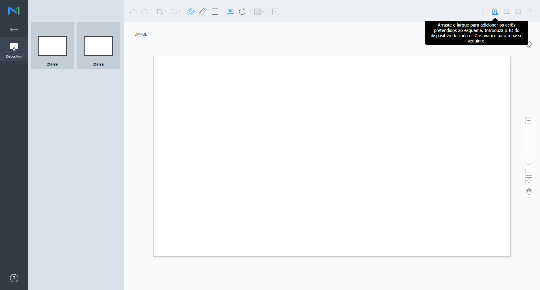
Introduza a ID de cada dispositivo e clique em 02.
Stylesheet class Ecrã do 
1 Permite apresentar a ID do dispositivo no ecrã do dispositivo relevante. 2 Permite inicializar a ID desse dispositivo. Ajuste as posições do dispositivo e clique em 03.
Stylesheet class Ecrã do 
1 - : Anule o último comando para voltar ao estado anterior.
- : Reponha um comando que tenha sido anulado.
- : permite alinhar vários dispositivos com base nos critérios de alinhamento pretendidos.
- : permite ordenar automaticamente dispositivos para se ajustarem ao tamanho da grelha.
- : permite apresentar a régua.
- : Permite apresentar guias.
- : permite selecionar o padrão de teste a apresentar no dispositivo.
- : permite pré-visualizar o dispositivo com o esquema aplicado.
2 Permite ajustar a posição do dispositivo de forma mais precisa. 3 Permite ampliar ou reduzir a vista de ecrã do editor. Utilize a barra de deslize para ajustar o tamanho da visualização. 4 - : permite ajustar o formato e a posição do editor ao tamanho da janela para obter uma vista geral dos dispositivos.
- : mova o dispositivo selecionado.
5 Pode rever as informações da licença de fonte aberta e a versão do VWL Layout Editor. - Após configurar o esquema, clique em Sim.
- O esquema VideoWall será guardado no servidor.
| Sv translation | ||||||||||||||||||||||||||||||||||||||||||||||||||
|---|---|---|---|---|---|---|---|---|---|---|---|---|---|---|---|---|---|---|---|---|---|---|---|---|---|---|---|---|---|---|---|---|---|---|---|---|---|---|---|---|---|---|---|---|---|---|---|---|---|---|
| ||||||||||||||||||||||||||||||||||||||||||||||||||
|